I was propmpted by a recent email enquiring about progress with this project to upload my most recent video of this, taken about three years ago, when I last had the opportunity to get stuck into this project. As you can see it shows successful swing up and stabilisation of a single pendulum. During this last phase of work, I realised that the sliding friction of the slip rings I was using posed a major modelling challenge, and I swapped them out in favour of wireless transmission of the second encoder position. The mechanical design, electronics and code build for this new element are now complete, so when I next have time to return to this, I'll be ready to start work on swing-up of the double pendulum.
 Despite appearances (i.e., no posts for more than three years!), I have been making steady if grindingly slow progress on this project. The reasons for this are a combination of other distractions (e.g. interesting jobs, moonlighting as a jazz musician - my other occupation - and having a young child), and my stubborn insistence on making every aspect of this project myself, which in turn has meant reconditioning my lathe, learning to use the CNC milling machine I bought myself, and so on.
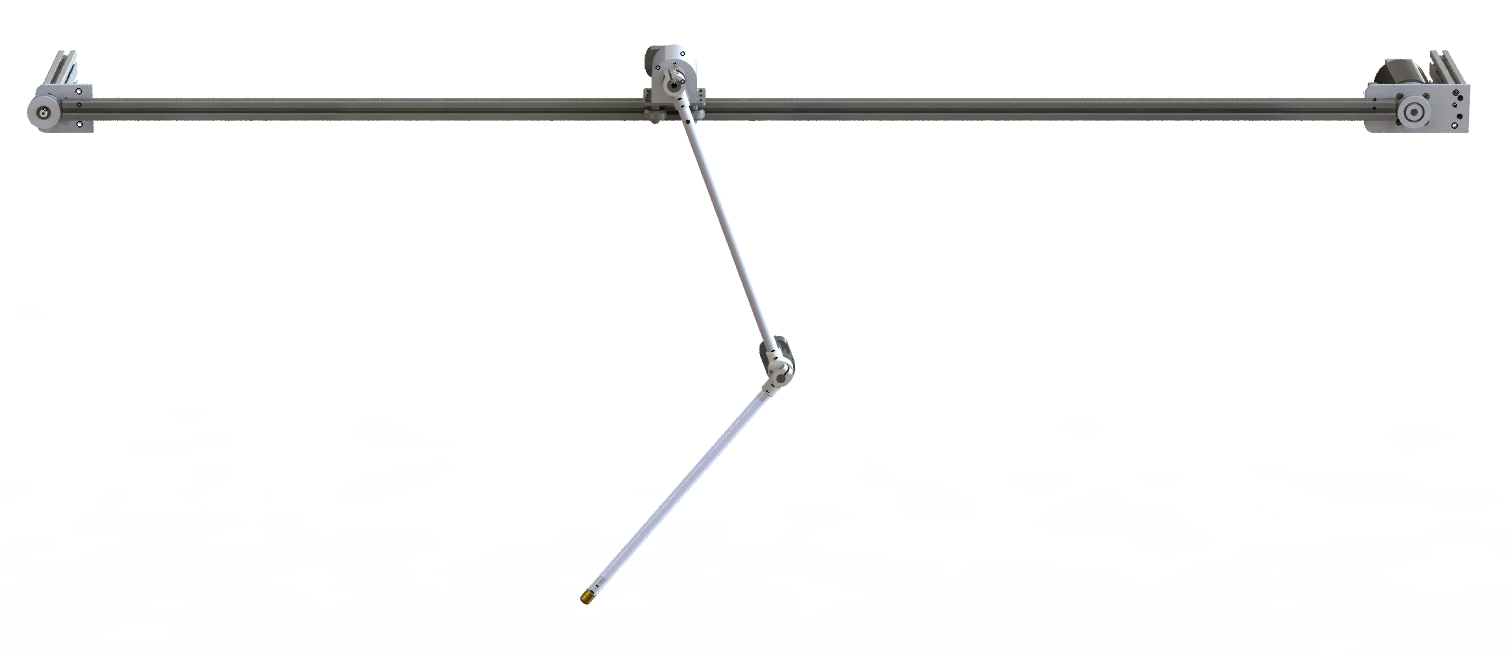
Anyway, I plan to provide a quick overview of progress to date here, and then dig into some of the details in future posts. So, what's been happening? Three main things: Choosing the electronics platform for the project, designing and building the mechanical components, and interfacing the electronics to the control software. Electronics After a brief flirtation with the Beaglebone Black, I had some exposure to an STM32-based controller for a haptic robotic controller at my then employer (Generic Robotics), and realised that it provided all the functionality I needed and seemed pretty straight forward to develop for. Consequently I selected a STM32f746 mbed development board which includes an Ethernet interface, hardware timers for incremental encoder quadrature, tons of processing power, and furthermore is absurdly cheap. I'm using the mbed environment to develop on, which brings with it lots of rich libraries including an easy to use TCP-IP stack. On top of that I designed a simple breakout board to hook up my three incremental encoders (one per DOF), and do some level shifting. I'm using an Electrocraft brushed DC servo which I had spare from an old CNC project, complete with 500 line encoder, and two AEDC-5560 5000 line encoders for the two pendulum axis. For a DC motor, torque is proportional to current, so I'm using a Maxon Escon 50/5 controller module (that's 50V, 5A maximum) with an integrated current control loop. I just have to feed it a PWM signal or analogue voltage proportional to the target current, and it will do the rest. Mechanical design This definitely deserves its own post, but I'll try and summarise the system briefly. I'm using V-Slot bearings and 1.5m long extrusion for linear motion of the cart. The cart itself is a piece of V-Slot standard plate with a custom designed body which holds the bearing assembly, encoders and slip ring. A loop of GT2 timing belt provides mechanical power transmission, and two custom machined plates hold the servo and timing pulleys. Short lengths of aluminium extrusion bolted to the two plates allow the whole assembly to be quickly clamped to a bench when I want to work on the project. The pendula are made from 12mm (10mm ID) aluminium tube. At each end are a pair of brackets which hold bearings and clamp onto the respective axles. There's an encoder on the back of each joint. The second encoder, between the two pendula, is wired via a through-hole slip ring on the back of the cart. Each joint consists of a machined aluminium axle supported by two deep groove ball bearings. Control interface I had wanted to rewrite the Matlab based controller to run on the STM32 development board, the idea being that I would transfer the nominal trajectories from the Matlab-based trajectory optimisation program to the controller, and then run the system independently of the host PC. Although this would be an interesting exercise, I realised that it's just a whole chunk of extra work, and the project is going slowly enough as it is! So instead I'm interfacing to the controller using UDP over Ethernet. I can achieve an update rate of up to 2 kHz using this approach. Unfortunately the in-built ethernet functions in Matlab seem to be extremely slow. So far as I can tell they open a new socket for every packet sent, which seems absurdly inefficient. In the end I found some example code for a compiled MEX ethernet interface that offered much higher performance, and I modified it to suit my purposes. I'll dig up and post a link to the original code soon, and my own if I can make it presentable. ----------------- What next? All of the above works, even if there's scope for improvement. I've started measuring the physical properties of the system, e.g. moments of inertia, joint damping, cart damping, etc, and I've begun running trajectories on the system, and using the trajectory optimsation library to generate trajectories using a model of the system using these parameters. I haven't swung the pendulums up yet, but I'm getting closer. More soon! Thanks for reading. I've been asked for plans for my toolchanger quite a few times, but I've always been a little reluctant to distribute them since I'd never really used it, and wanted to make sure there weren't any fundamental design flaws. Well, that all changed Friday night (yes, Friday night -- I know how to party), when I finally battled through Mach3's somewhat non-functioning (for me anyway) tool offsetting system. I had two tools loaded, and made a small part successfully. All tool changes completed flawlessly, and I'm looking forward to getting the changer decked out with a full complement of tools. Now, a couple of caveats: I think the toolchanger is a little over-engineered. While it feels rock-solid (which is the idea), it's also very heavy and quite big. The size is an issue because it soaks up x-axis range, effectively using up part diameter. I can improve this straight away by redesigning the 'Base' part on which the changer sits. Currently this extends 15mm beyond the toolchanger side. You screw the two together, then screw the entire assembly onto the lathe cross slide through holes in the overhang. It would be better to screw the base to the cross slide, then have through holes on the tool changer to allow it to be bolted to the plate, eliminating the need for the overhang. I've worked out how I can modify the toolchanger I've built to accommodate this, but it would be better still to slightly redesign it this way from the start. And generally I think it could be a little smaller and less heavily built without much if any compromise to the performance. So, with that in mind, here's a zip containing a step file with the whole assembly. If you use these or they inform the basis of your own design, I'd be grateful for a credit and a link back here. Thanks!
This is a big project I've been thinking about in some form for a couple of years but only really started on in earnest a few months ago, after taking the MIT/edX Underactuated Robotics course. After taking that course (well, most of it - I ran out of time to finish, but it's on my to-do list!) I realised that the techniques I'd learnt about should allow me to build a controller for a double pendulum cart.
Incidentally as an aside, if you're interested in robotics and control, and are looking to go beyond the classical control material that you learn on an undergraduate engineering degree, then I really recommend that course. For years MIT has been putting a lot of the content from its courses online for free, but unfortunately it's a bit of a mixed bag. Occasionally you'll find a complete course - videos of lectures, notes, problem sets and answers etc, but most of the time it'll only be the notes or some lectures. Even if everything is there it takes quite a lot of self discipline to work through it all to the end. The edX version of the Underactuated Robotics course is incredibly impressive. The lectures are released to a schedule with accompanying (autograded) problem sets and a forum where all enrollees can discuss the course. It's actually pretty amazing that this content is available at all without actually being a student, but this way of delivering the material takes it to the next step - it's probably the closest thing to doing the course in person. Anyway, back to the pendulums. I've actually written an overview of the project with some videos, but in short, a double pendulum cart consists of a cart free to travel along a linear rail, with two pendulums in series dangling from the cart. The only actuator is a force input into the cart parallel to the rail - the pendulums are completely unactuated (hence it's an underactuated system, in this case one actuator, three degrees of freedom). The challenge is to design a controller that can swing the pendulums into the vertical position, or some other stable pose, e.g. one pendulum hanging down and one up, and to keep them stable in that configuration in response to disturbances. Right now the project consists of a small trajectory optimization library that implements a technique called direct collocation, plus various supporting functions for closed loop control, animation, derivation of equations of motion etc, all implemented in Matlab. Using this I've successfully generated swing up trajectories, and the closed loop controller seems robust enough to cope with quite large perturbations of the system initial conditions etc. I think I've got almost as far as I can in software, and I need to start thinking about how to actually build the system for real. More on that next time... Like a lot of people I consume a huge amount of engineering and hacking content on the internet, but am pretty terrible at documenting my own projects. That's not to say I don't like to talk about them, but outside of my engineering colleagues, that generally means cornering my brother and trying to explain to him why balancing pendulums (or whatever it might be) is not only a cool but also worthwhile and challenging thing to do. On my most recent conversation with him on this theme he suggested I should start a blog (something I'd been mulling anyway), where I might find a more interested audience!
I've also been intending to put my projects up on hackaday.io, so I'll probably share some/all of the content between the two. I could just host everything on hackaday but I'm not entirely sold on the layout/format of their site, and anyway I want more control over the content. I suspect I'll probably put all the gory details here and edited highlights on hackaday.io, but I'll see how it goes. |
LukeArchives
March 2024
Categories |
||
 RSS Feed
